I actually thought after finishing the fusing (All 2400 of them) that I was done! Just hook the cels up right? No, I was clearly mistaken. The steps that I still had left were just as time-consuming. In my mind, I was done. As you will see in this post, I still had the BMS to sort out, I had to balance all the cell packs and also get my solar installed.
Let us start with the BMS
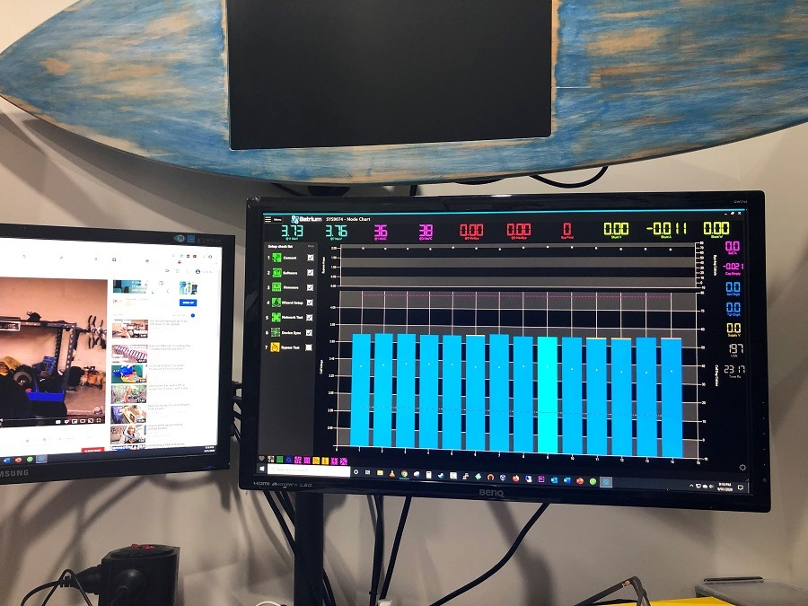
 As mentioned in other posts I ended up purchasing the Batrium Watchmon 4 14S kit with expansion board. At the time, this was the ‘bees-knees’ of Battery Management Systems. It comprises of the main and unit and the Longmons which attach to each cell pack. The longmons look after the voltage of each pack, basically it burns off excess power to keep each cell pack balanced with each other. The Longmons and Watchmon 4 kit is not an active balancing unit. More of a passive balancer. The Longmons also have a few other functions, such as temp monitoring and feeding of this information back to the Watchmon. See the latest Watchmon 5 for a more centralized approach to battery management.
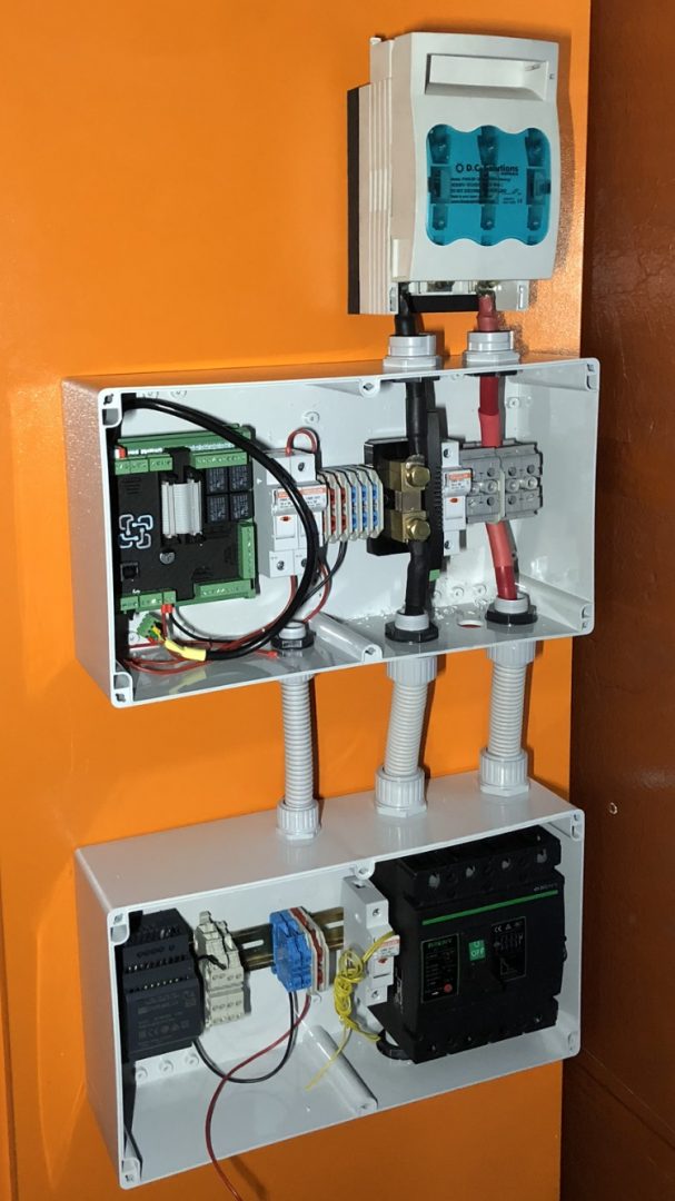
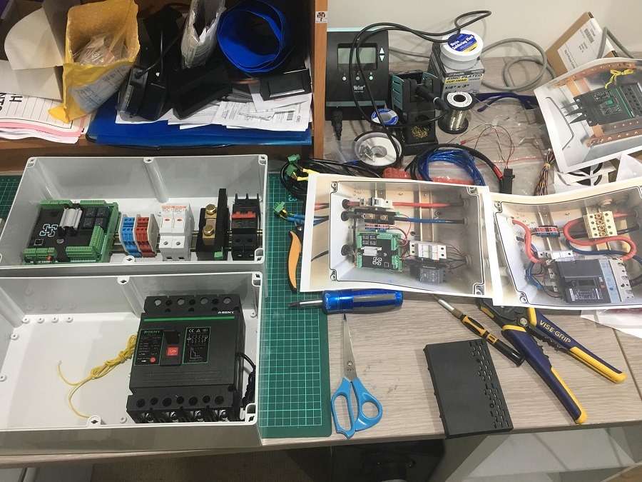
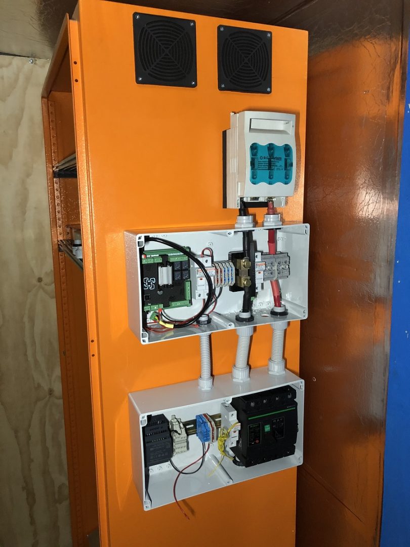
I ended up finding a couple of clear front enclosures and mounted the BMS inside on some DIN rail. Originally I thought I would mount the gear on the same wall as the inverter, but after some thought and worry about running out of space, I decided on mounting on the cabinet itself. This part was probably the most complex of the build, but it’s pretty straight forward to follow once you have all the parts.
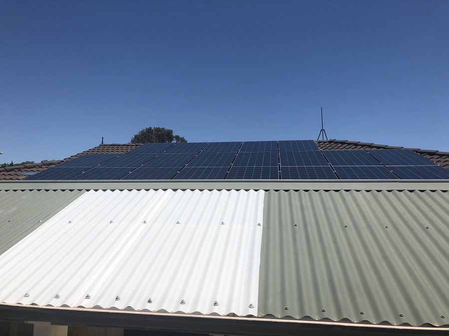
My Solar (Finally) Installed
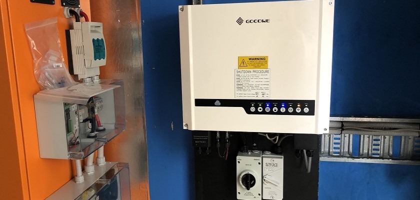
 After much procrastinating, I decided upon the Goodwe GW5048D-ES Inverter. It is a 5Kw Hybrid inverter and has a lot of the features I needed. The first being a 48v suitable charger for the batteries. The spec on the charger is up to 60v @ 100A charge/discharge. At 48v that is a lot of current. I think I’ll run it at 50A first. The other bonus to using this inverter is the ‘backup’ functionality. It has a built-in UPS type function in which it can switch to battery during a power outage. I’m not really sure I’ll be using this just yet, but other inverters require separate hardware to make this happen.
As for solar panels, I ended up getting a good deal on some 315w Link Energy panels. Now a lot of pros and cons going for a less than known brand, however, my main considerations were; They must be considered tier 1 panels, they must be on the CEC approved list and they must have a good warranty that can be executed directly in Australia. They seemed to tick all these boxes so I pulled the trigger. (Hopefully, this theory works for me, could come back to bite me.)
A quick mention of the cable tray and gantry into the shed
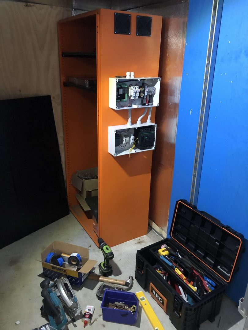
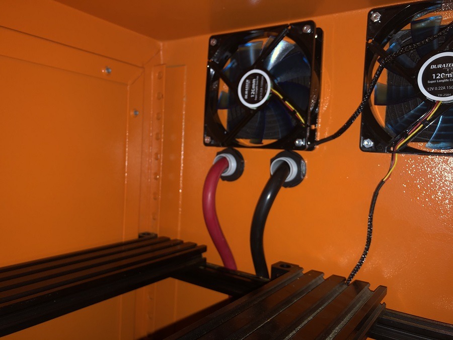
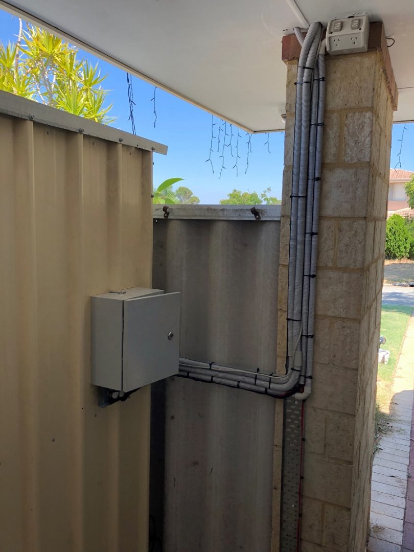 It seems a lot of people don’t exactly get their inverters installed in a small shed. I had to be confident I could keep the space cool and that I could get all associated cabling in the shed safely and be accessible to the battery cabinet. I ran some 75mm cable tray down a concrete wall and around into the shed. I then installed a large box to act like a gland. This should allow for future expansion and putting the Xmas lights in/out as required. I also installed a couple of runs of cat5 and got the sprinkler controller/cable to come in as well. I will be covering the cable tray with some cream-colored sheet metal. I am yet to get this priced up.
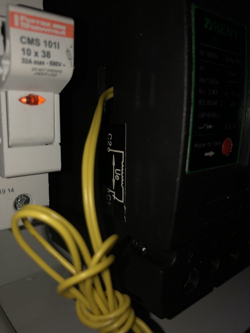
Trip Shunt Install
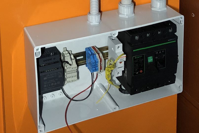 The ZJ Beny Trip Shunt I also installed in a similar fashion to the BMS. Its a tight fit, but with some carefully placed glands I can get the 35mm2 cable in/out. (I may need to drill them out for the lug thou!) The trip shunt is controlled directly from a relay on the Watchmon 4 expansion board. I have installed a Meanwell DC-DC power supply to feed 24vdc to the trip shunt (Via the relay). When the Watchmon activates the relay because of a ‘critical fault’ it will activate the trip and cause the ZJ Beny breaker to be turned off. It was interesting to note that during my testing, I was required to turn the 24vdc power off first before I could reset the unit. This kind of made sense, but took me a little while to figure it out.
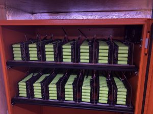
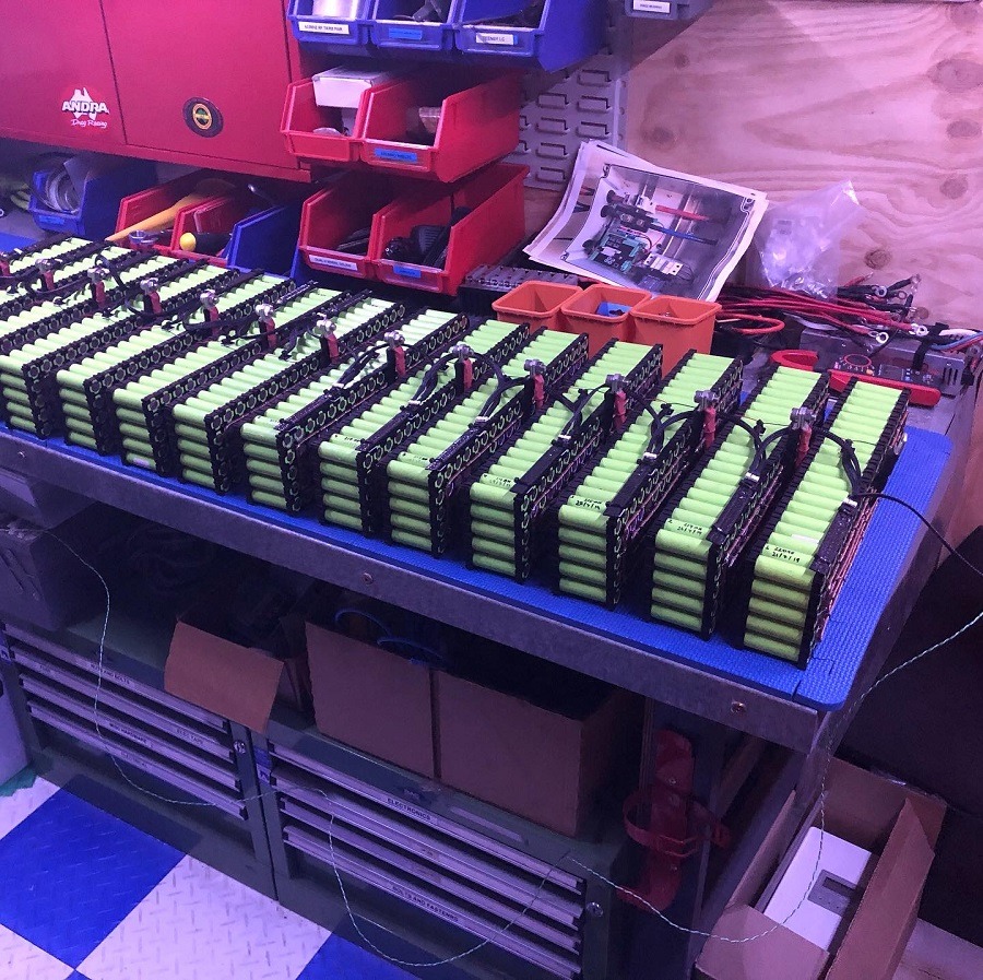
Battery Mounting in the Cabinet
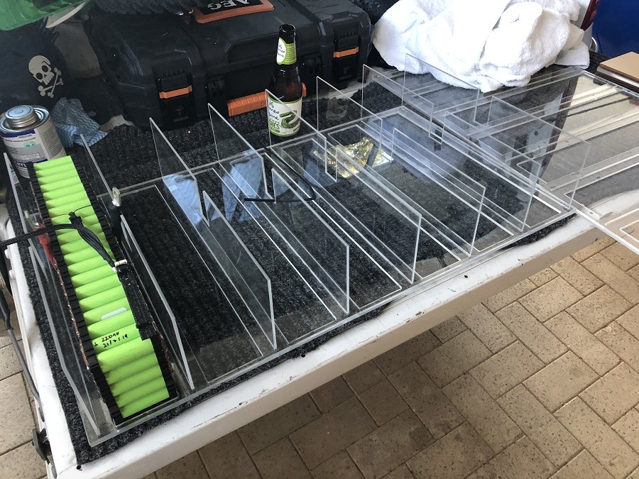 If you have been following along in the last post, you would have seen that I tried to build some funky perspex holders for the cell packs. I ended up throwing this idea out and going with something a little bit more simple. I ended up using the laser cutter and
router to make a permanent shelf with side protection. The 6mm acrylic base was routed to seat 7 cells and the 3mm acrylic used to slot into the base as side protection. I glued all these parts together using acrylic glue and it seems to be very solid. This approach means that I can disconnect a battery and just slide it straight out to work on it. I won’t have to mess around taking apart the last design.
So what now?
Well apart from finishing the wiring in the BMS enclosure and running the battery cable to the inverter, I need to start looking at how the Batrium BMS interacts with the CANbus. I’ll get back to you soon with how the connection went!
A couple of pics from progress thus far!
If you missed the first parts of the build.
Part 1 – Recycling batteries
Part 2 – Building Packs
Part 3 – Fusing and cell protection