Well, that’s a wrap!… Kinda. I have had some very mixed results when trying to commission the whole system. If you don’t feel like reading the whole article, the main problems were with the inverter and how the BMS interacted with it. The CANbus/BMS integration that I had assumed would work flawlessly did not really work at all. It seems that when companies make hardware too smart you run into WAY more problems. I’ll do my best to go into it all a bit further below. That aside, all the equipment is wired, running and as you will see to some degree up and running.
Battery Connection
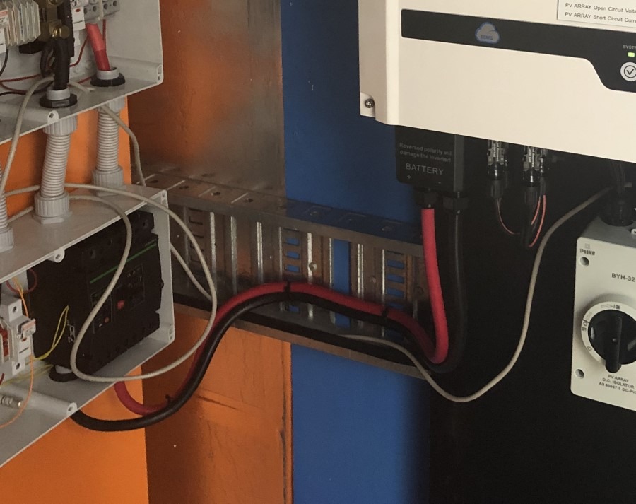 The first item on the agenda after the last post was to connect the batteries to the inverter. This was super simple. A couple of lugs later and voila done! The only issue I ran into was that the 35mm2 lugs I used would not fit through the cable glands properly. Lesson learned, terminate the cable after feeding through the cable gland. If you’re running a GW5048D-ES then it suggests 25mm2 cable which would probably fit with the lug through the gland, but I decided on a heavier gauge cable. Also, try and keep the cable run short to minimize any voltage loss on the cable. You can calculate this but at less than a meter, I assume the cable loss would be negligible.
Batrium CANbus to Inverter Connection
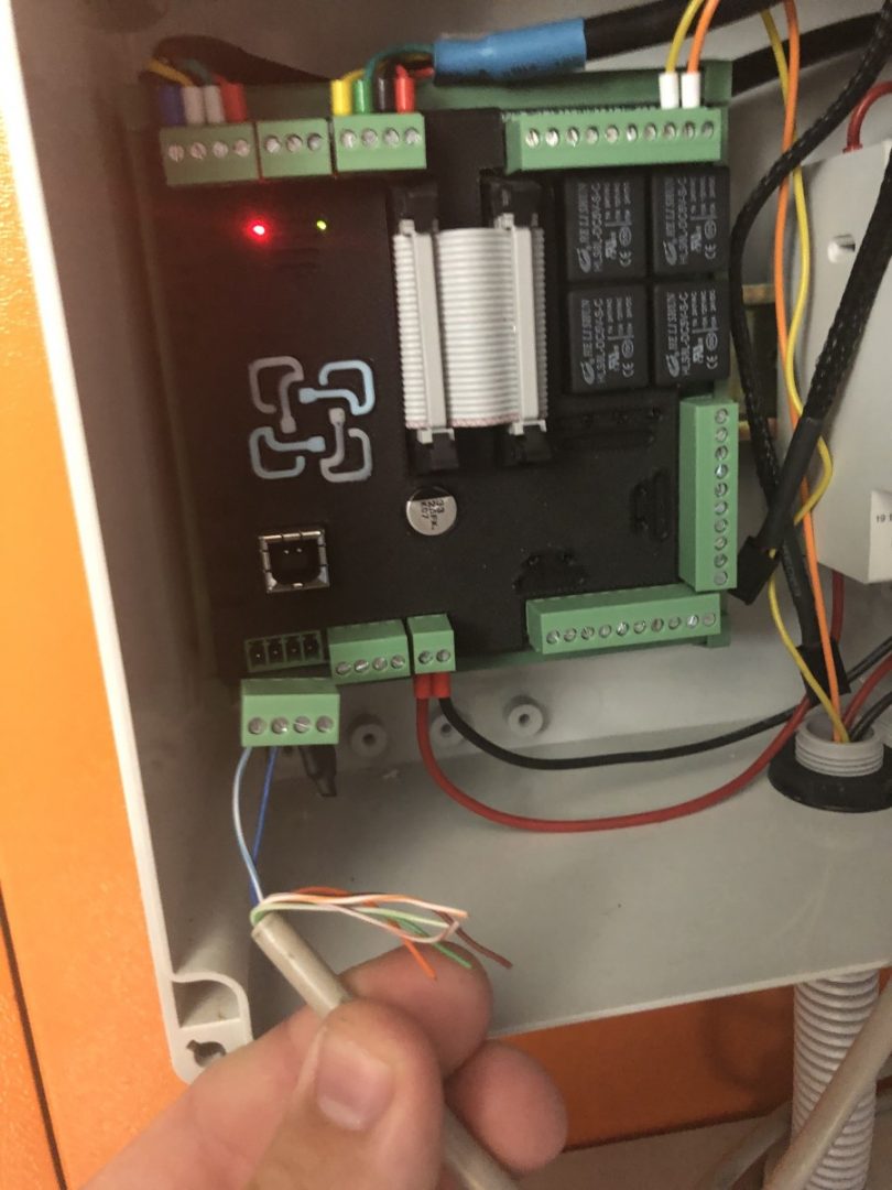
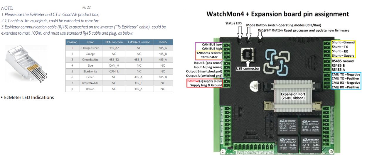
This had me stumped for a while, however, we eventually got through it. The GW5048D-ES came with a dedicated BMS cable. This cable at one end only had 3 pins terminated. After a bit of investigation, I found that the Blue pin = CAN-H, White/Blue = CAN-L, and the Orange is GND. In the image gallery below you can see the extract from the manual. Now I am no expert on the CANbus protocol but it seems that having a 120ohm resistor on each end is pretty important. The Batrium Watchmon 4 came with the resistor installed and I was able to find some clear instructions on the Batrium website for which pins to connect to.
At first, I did not connect the GND pin, It still seemed to work, however, I eventually connected it with no significant change in performance. Also of note is that I connected the BMS cable from the BMS port on the inverter to the CAN/H/L pins on the Watchmon. See the Gallery below for a few pics of connection.
(Almost) A complete Failure
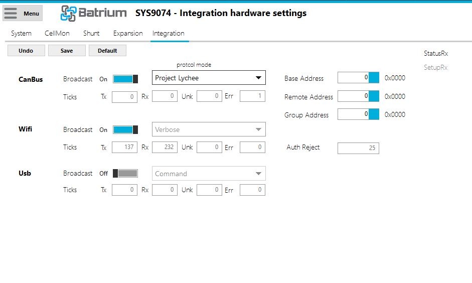
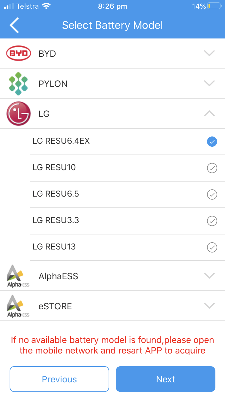
After connecting the CANbus cabling, I attempted to configure the Batrium software to talk to the Inverter. As it turns out the only way I could get Batrium to talk to the inverter was in the integration settings in Batrium and select the “Project Lychee” integration. This integration mimics an LG RESU 6.4 battery. Thus on the Inverter and inside the PV Master App (Goodwe Configuration Tool) I had to select the LG RESU 6.4EX battery type. I was then able to confirm in Batrium that CAN comms were working. What you need to look for is that batrium transmits and receives.
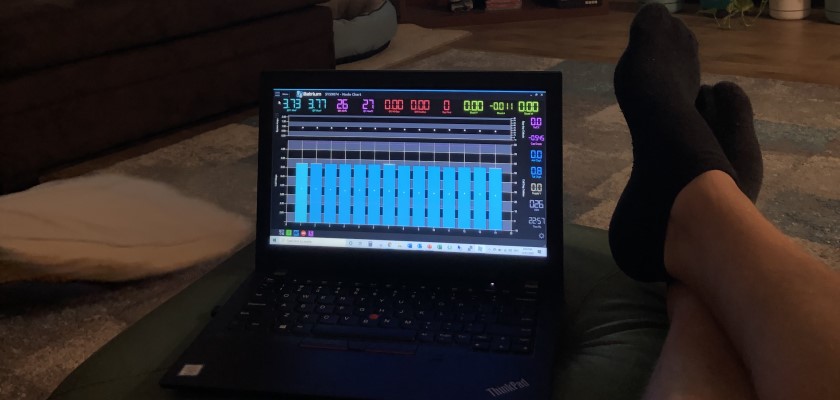
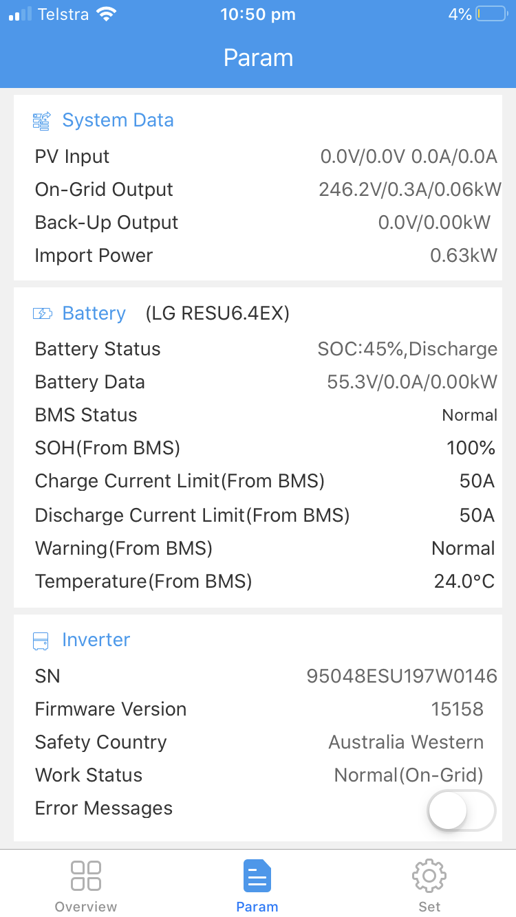
Now that I had Batrium Communicating with the inverter, surely it would just be a few tweaks of Batrium?… How wrong I was. At first, all looked good, the charge cycle completed at the values I had set in Batrium and all was well. I started running into issues during the discharge cycle. The inverter could not make up its mind if it wanted to discharge or sit at idle. As you can see from the video below, keeping an eye on the “Shunt A” value. That is what is happening on the BMS shunt.
So where am I at now?
So after much back and forth with both the Batrium support team and Goodwe, no one can or wants to help me. I paid $85 for Batrium support in which they basically told me it was an inverter issue and Goodwe told me to use an approved battery. Boooo! So, for now, it looks like the remote integration is a no go. Not all is lost though, the inverter actually has a “self Define” battery option. This option is designed for Lead Acid batteries and has a few settings that can be configured. Such as Battery Capacity, Voltage Charge Target (56.7v in my case), Charge/Discharge Current (20A/20A to test.) and some SOC protect percentages. I have since been using these settings for a few days now with no issues. The inverter charges nicely and cuts of at set voltage. I am yet to run the battery down to test the SOC protect. That is next on my list.
If you missed the first parts of the build.
Part 1 – Recycling batteries
Part 2 – Building Packs
Part 3 – Fusing and cell protection
Part 4 – That’s a wrap
Hello, I also have a goodwe investor. I am testing with the self-defined configuration. I have made a battery of lifepo4 16S and BMS daly. Do you have the DOD data for 56V?
Hi Alfonso, I never really had much luck allowing the Goodwe inverter to track the Depth of discharge. It would always stuff up after a week or so. Hence the reason for using the CANbus of the BMS to report the results directly. I’d get a ZEVA BMS or Batrium and go the CANbus route.
Hi. I’m also having trouble. What did you set as the Canbus intergration is in batrium? Did you select goodwe settings and self define in the PV app?
Hi Dan, the canbus won’t work if using self-define. Of note, in that mode, the Goodwe really struggles to track the SoC of the battery. This only worked for me for a short period before It would basically lose track. Which goodwe are you using? I ended up having to replace the GOodwe smart meter that come with my kit. Goodwe sent me a new one for free, which kind of indicates to me that its a known fault! Once I swapped the smart meter and reattached the RS485/Canbus connections, Batrium was able to ‘speak’ to the inverter and it actually did what it needed to do. THe inverter then used Batrium SoC to control itsself. Much more reliable and accurate than the self defined mode.
Hi Dwayne – interesting stuff! I hope you don’t mind me asking for some advice.
I’m working on DIY battery storage, potentially to be incorporated into an EV conversion, and using some similar components to you. I have a Goodwe 6000-BH inverter, and am failing to get it to work in self-define mode. Goodwe have responded to support emails but have now closed the ticket as I’m not doing what they really want to support.
In my system, I only want to use the Goodwe to discharge the battery. I’m charging it using an Elcon EV charger, and monitored with EMUS BMS, which also monitors SOC and will stop the discharge at a set level, and so I don’t need the BMS connection to the Goodwe. My battery is at around 120V, but within self-define battery I seem to be limited to setting a battery level at 200V at the lowest. However I don’t think that should matter, as with DOD protection switched off, I think the inverter should just keep discharging. I’m using it in Eco mode with only a discharge profile configured.
I’d be grateful of any tips on how you got self-define to work!
G’day Lynden, I hate that self define mode! it has a terrible time tracking SoC. At first, it’s good, but over time it drifts and is terrible! Interesting project though. Do you have any other reference materials for this project? Application? EV?