Only 1 things has slowed down the progress of the electric vehicle build, and that was the arrival of the Onefinity CNC router. However, for the most part its done and we can move on. Check out the build below.
What is the Onefinity CNC?
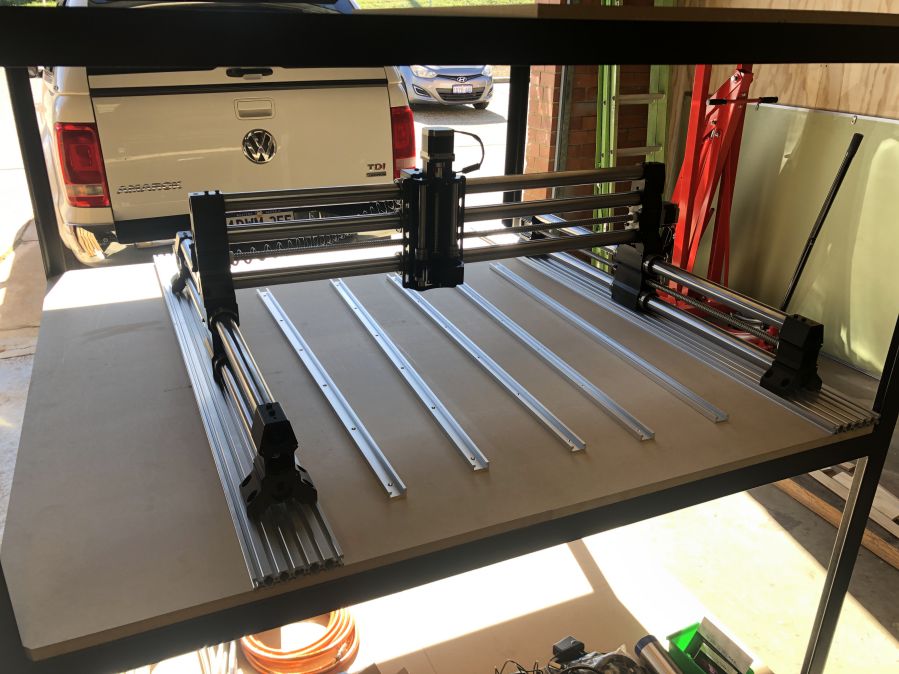
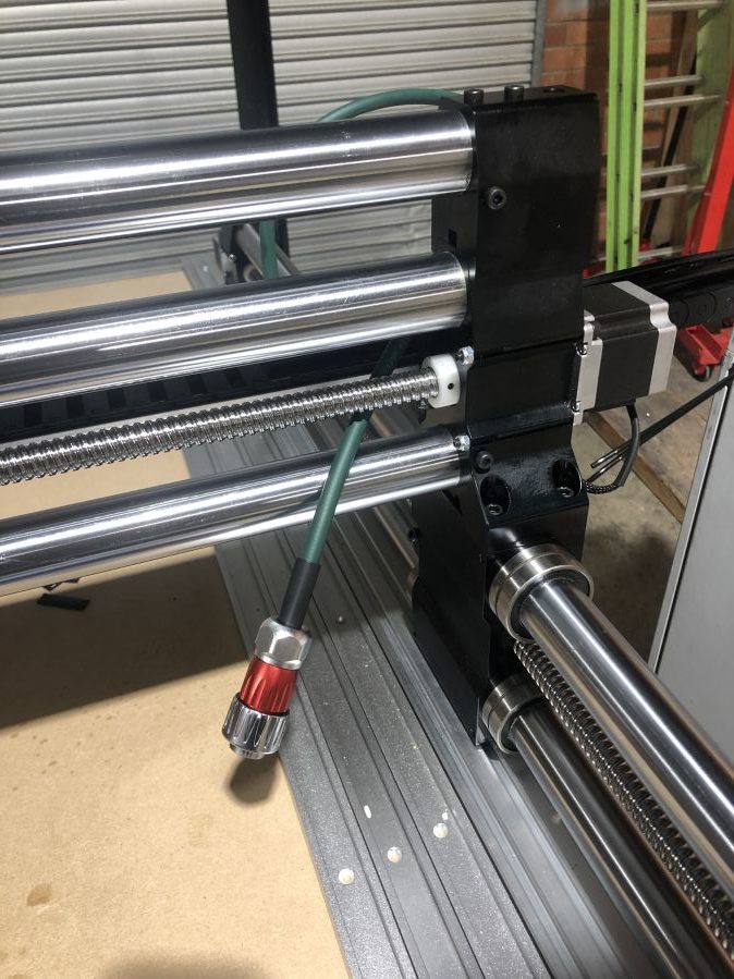
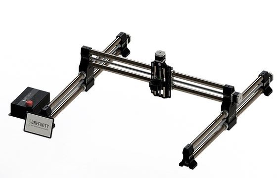 The Onefinity (1F) is a different take on a Desktop CNC from the guys here. They market this particular machine as “reinventing the CNC experience” and for good reason. The biggest difference between this machine and others is the fact that they use hardened steel cylindrical shafts on all axis with ball screws to provide the motion. No belts, no wheels, just solid movement across all axis. This system seems very robust and can operate at higher speeds than using wheels and belts. With better accuracy as well!
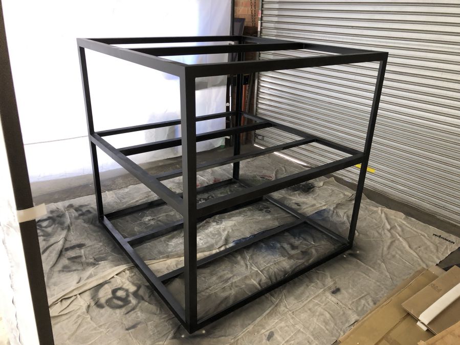
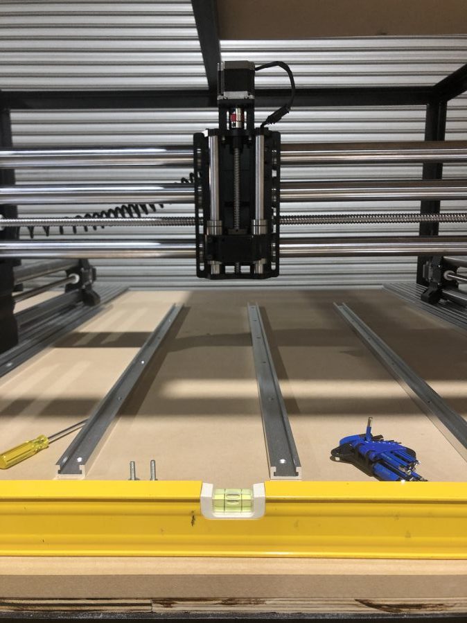
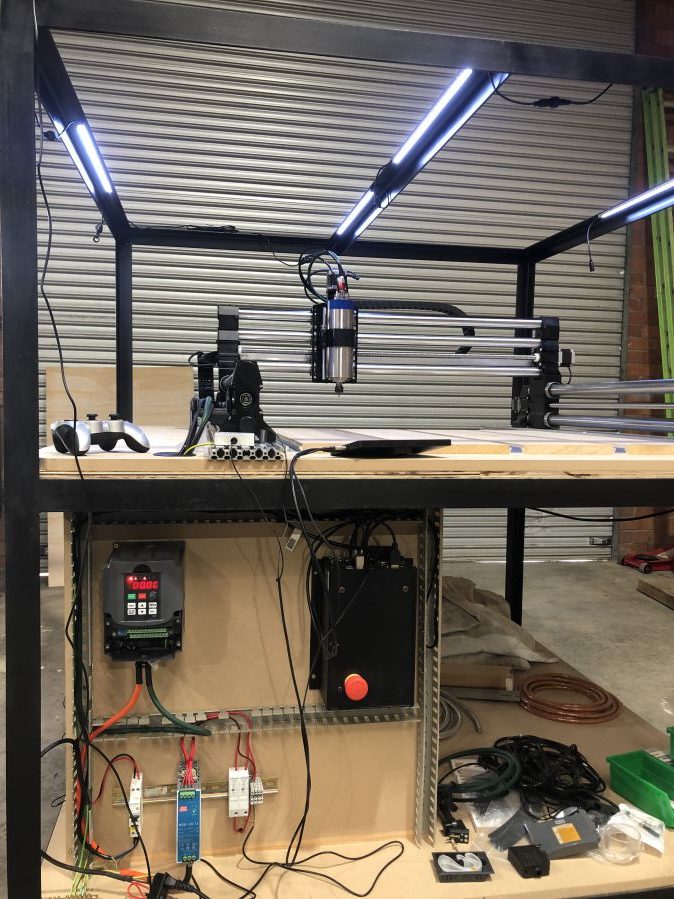
Step 1: The Enclosure.
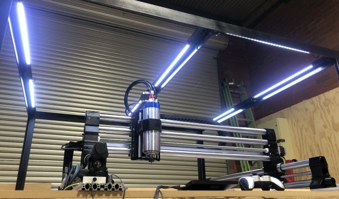
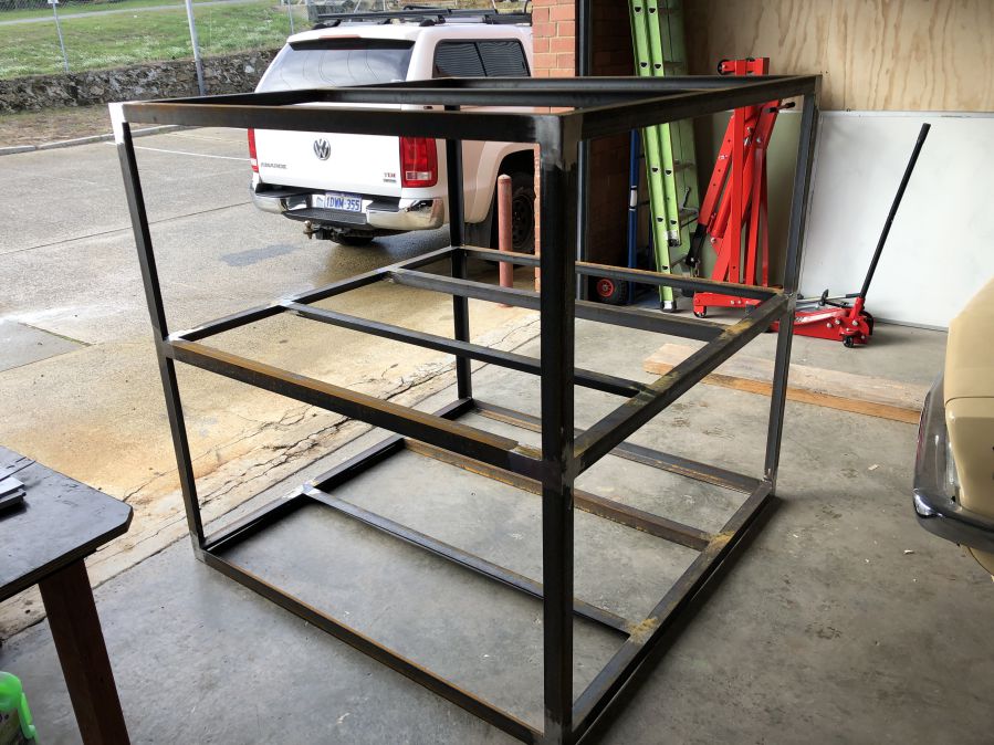
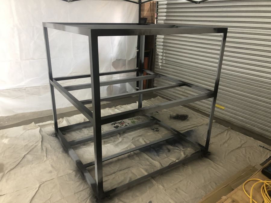
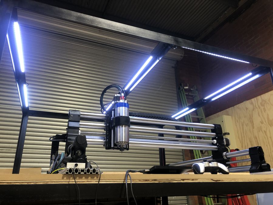
Even before getting the new 1F Woodworker into the workshop I decided to get an enclosure built. My aim here was to enclose the whole CNC so that I could put a job on and actually hear my own thoughts in the shop. Not sure if you have heard a spindle cutting at high speeds, but it can be loud! The enclosure needed to be solid. This is what we ended up with.
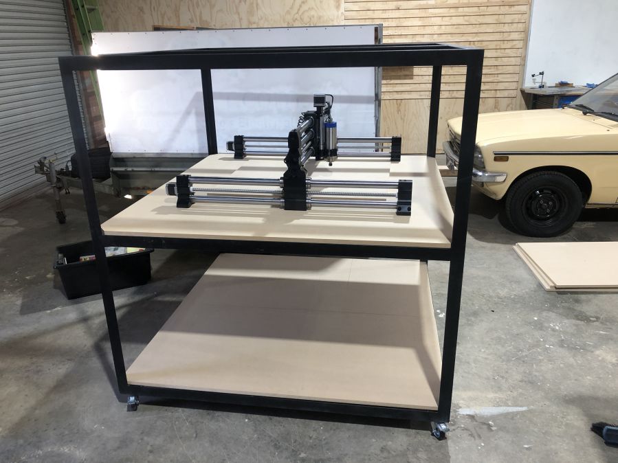
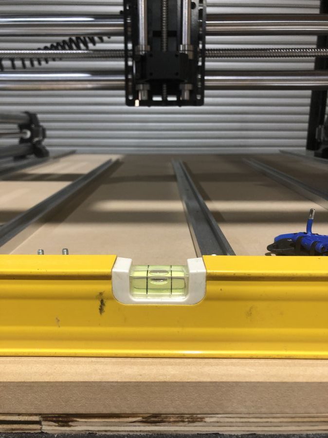
Step 2: Attaching the Onefinity
Most setup videos will guide you through attaching the 1F to a wooden base, however I was not sold on this idea and had a few lengths of Aluminum V-slot hanging around. It turns out the mounting holes on the 1F marry up nicely to the slots and I was able to use some T-Nuts to secure. The Vslot itself is secured to the wooden top using some large coach bolts at either end.
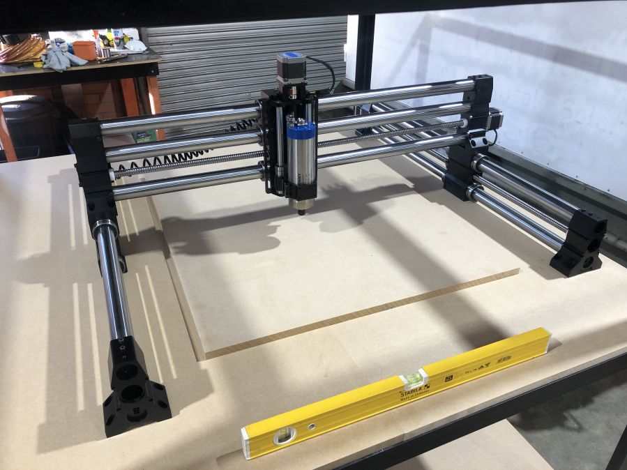
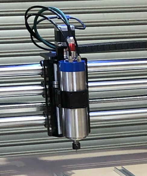
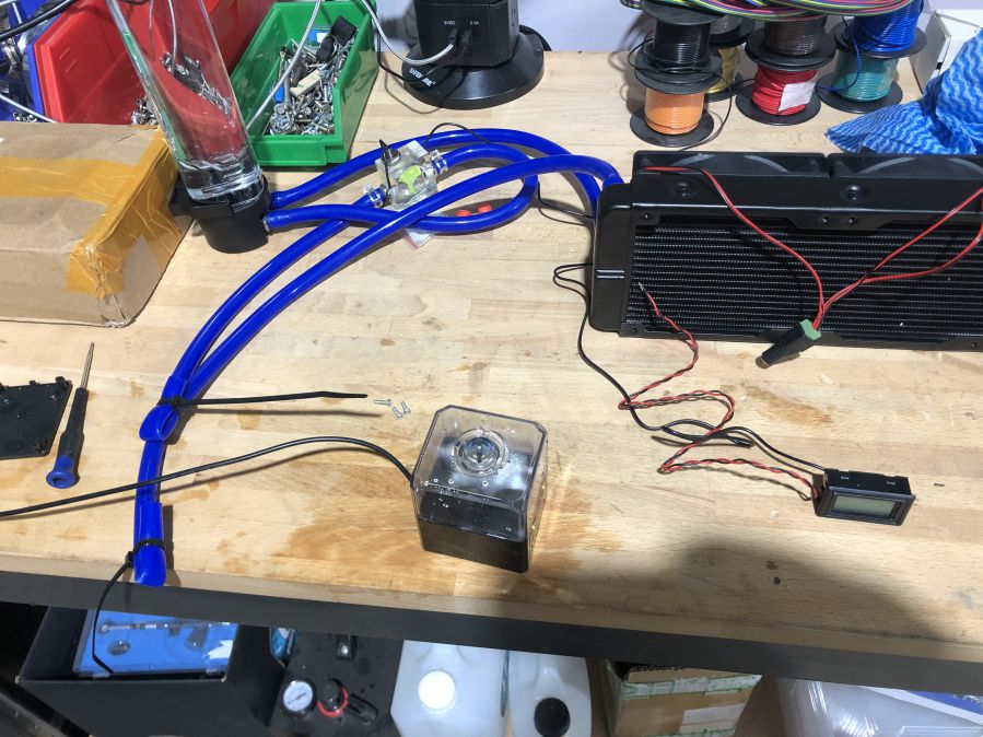
Step 3: Spindle
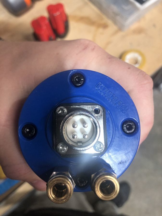
The default 1F build comes with a Makita Hand router that mounts into a 65mm spindle mount. These are very loud routers and decided early to go with a VFD controlled spindle. This kind of setup is not supported by Onefinity, however they do now sell an 80mm Spindle mount which will accommodate most 1.5kw and 2.2kw spindles. I ended up purchasing a 1.5kw water cooled spindle and HuanYang VFD. The spindle comes with an ‘aviation’ type 4 pin connector. These are ok, but decided to upgrade to a more robust connector. Whilst I was at it, I checked to make sure the spindle had Pin 4 connected to ground. Often these Chinese spindles do not have an earth connected which can be dangerous in a fault situation.
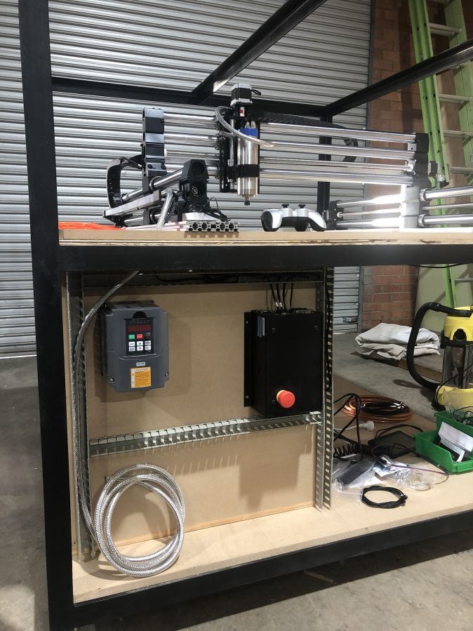
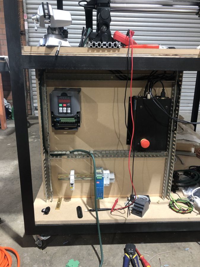
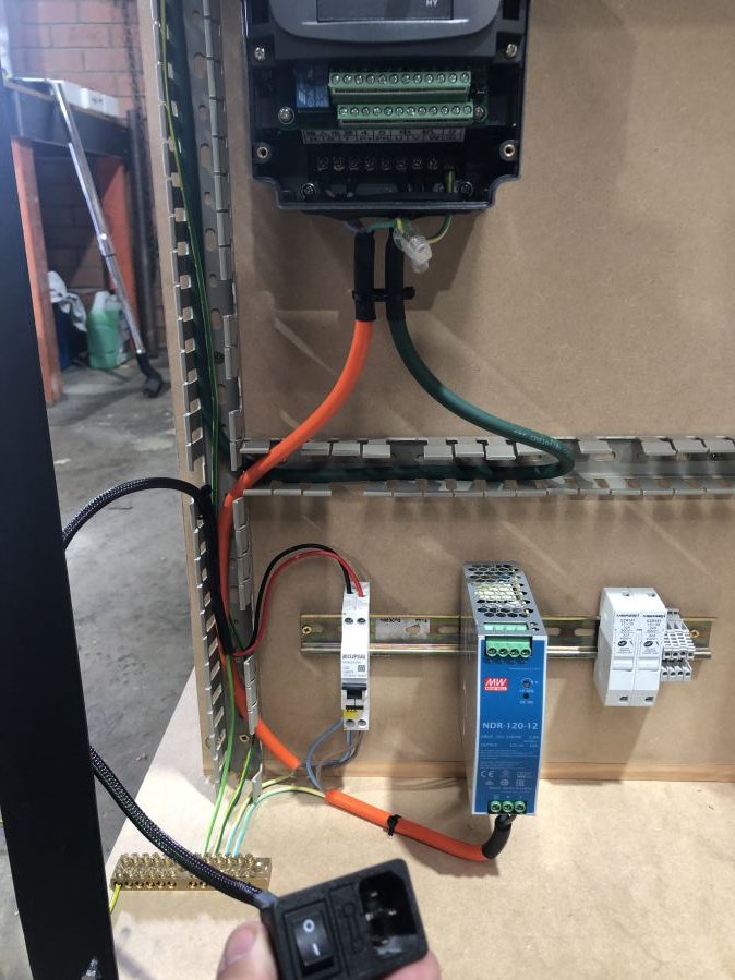
step 4: Electronics and Wiring
I’ll try and keep this brief, however the electronics and wiring can be broken up into a few areas: (CONSULT AN ELECTRICIAN!)
VFD and Spindle: The VFD requires a single phase 240v input, I ran the main input through an RCBO and up to the VFD, This provides some protection to the user, I also made sure all parts of the spindle, frame and router itself were earthed. From the VFD I wired a shielded control cable up through the cable management to the Spindle. This is a 3 phase 220v cable and needs some caution when running and connecting.
AC-DC for 12V Components: We also wired in a Mean Well AC-DC power supply to provide 12v DC to the LED Lights and the Spindle cooling pump.
X/Y Servo Motor extension cables: The cables supplied by 1F are not long enough to run through cable management, thus we had to build our own. The pinouts and types of connectors are readily available in the Onefinity forums. We made one piece cables so that no connections were being made inside the drag chains.
1F CNC Controller: This uses a singular 240v (or 110v) IEC cable depending where you are in the world. These are pretty common.
Earthing: All earthing, including the VFD comes back to a service earth bar.
Step 5: Everything else!
What is left! Spoilboard, some surfacing of said spoil board, some cladding for the frame. etc etc. I’ll update this when it’s complete. In the meantime enjoy the rest of the pics from the build.